Automated Nerf Turret
More Nerfturret 16 Mar 2015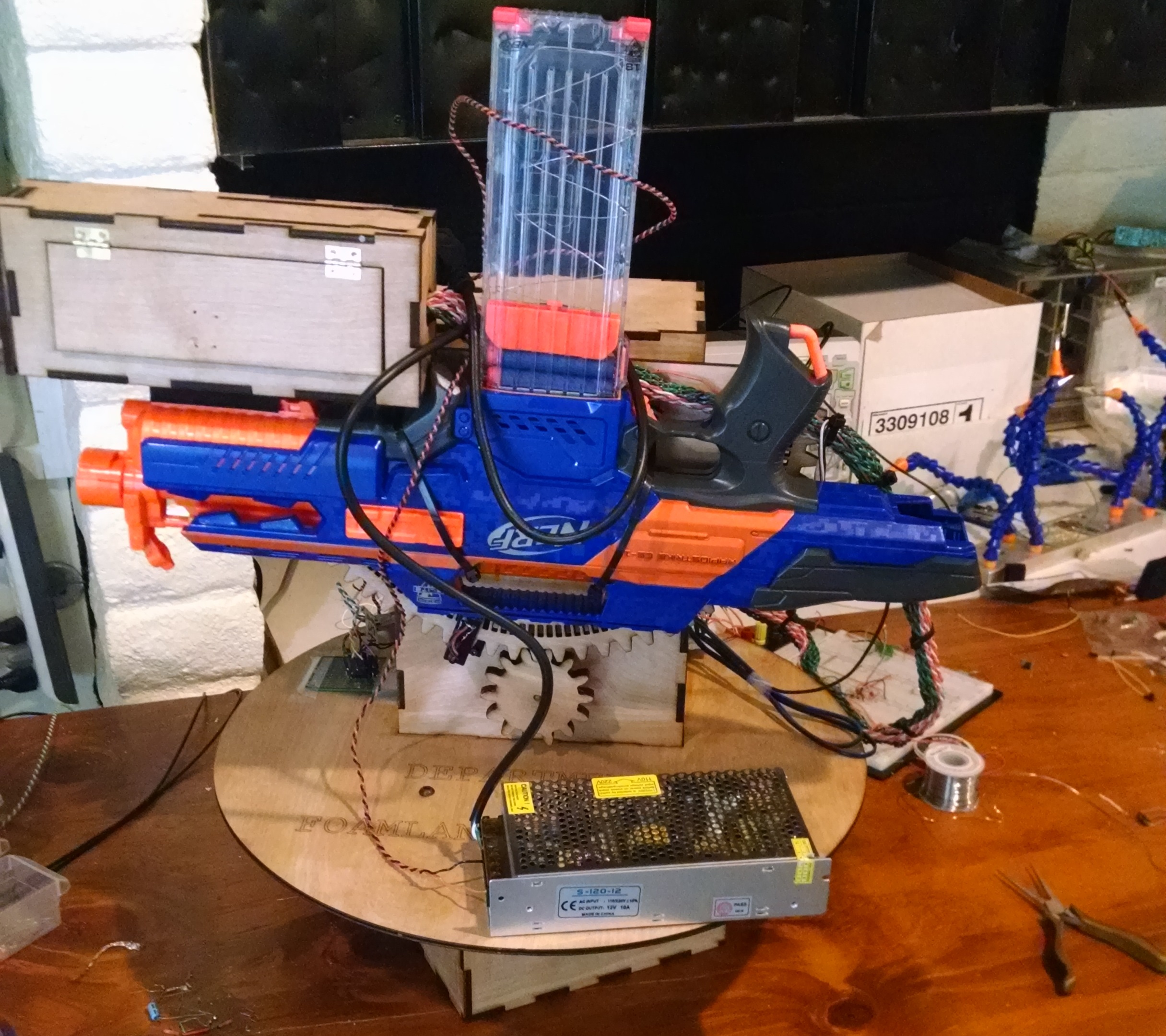
My final project for my Mechatronics course at Cal Poly. We (myself and Colton Crivelli) had to build an Nerf gun that could autonomously find and shoot an incandescent bulb mounted to a square piece of wood. The project was titled “Learn by Duelling” since our turrets would compete against each other in duels, and Cal Poly’s motto is “Learn by Doing” (hardy har har).
If you’re crazy and you know this ridiculously long post isn’t going to be enough excruciating detail for you, or you want to see how gorgeous a LaTeX paper is (Thanks Andre Miede and classicthesis) then check out the full report here. Otherwise, read on for a surprisingly in-depth overview.
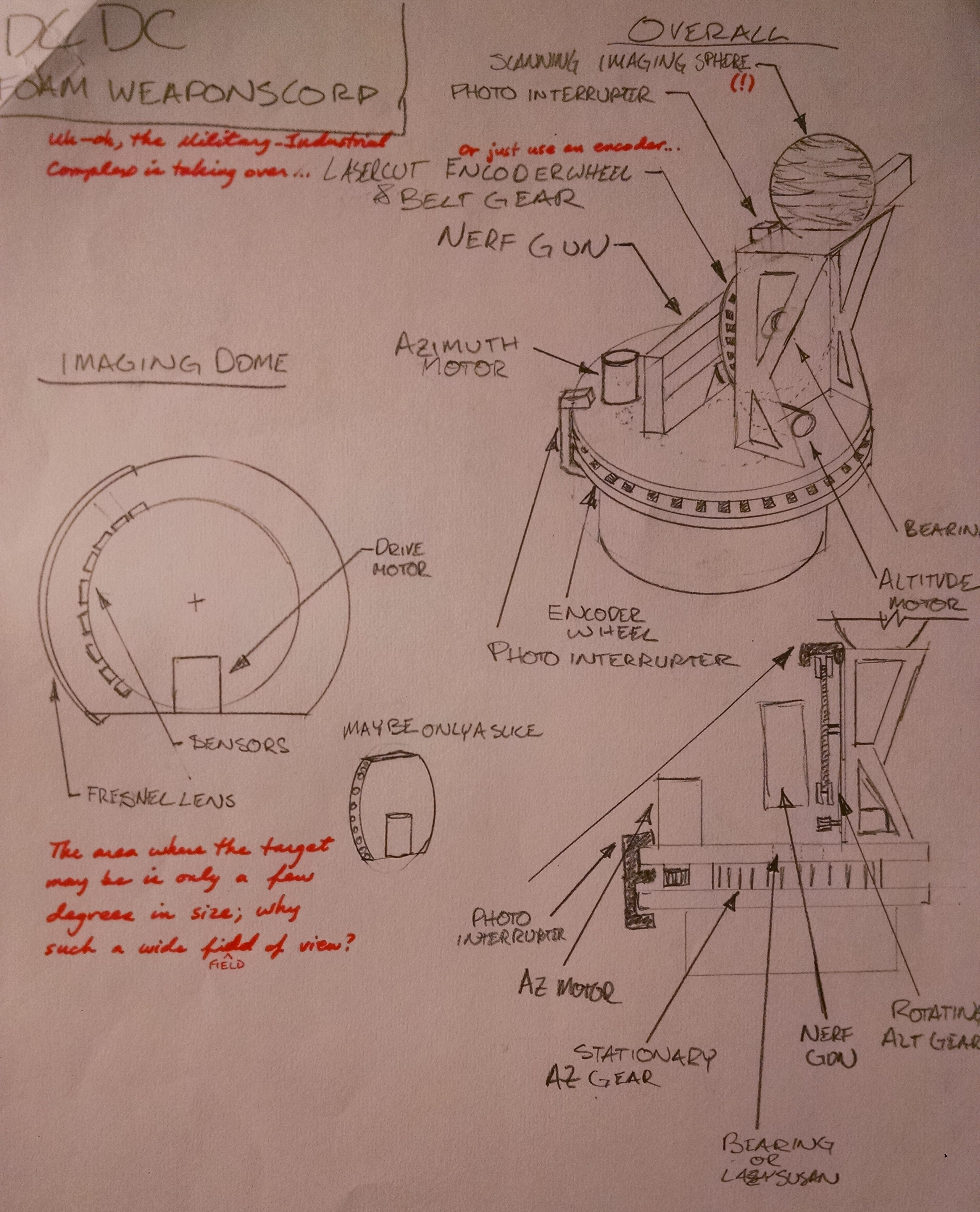
This is where the design started out, with a quick sketch we had to whip out in lab to show our teacher where we were headed. I was mostly in charge of the physical design, while Colton was in charge of the software design. The main difference between this sketch and the real implementation was the scanning imager. We wanted to have a continuously rotating scanner (like LIDAR or something) that would immediately find the light bulb target so we could move instantly to the firing position, rather than searching around. Sadly this had to be shelved for a few reasons. One, Fresnel lenses can’t be curved like I drew one and still work how I wanted. Two, we needed to have a rotary slip connection to get power into the imager and ain’t nobody got time for that. Finally, the imager should have been located right on top of the gun. As it stands, the angle between the gun and the imager, if they’re both pointing at the same target, is dependant on the distance to said target. So that sucks.
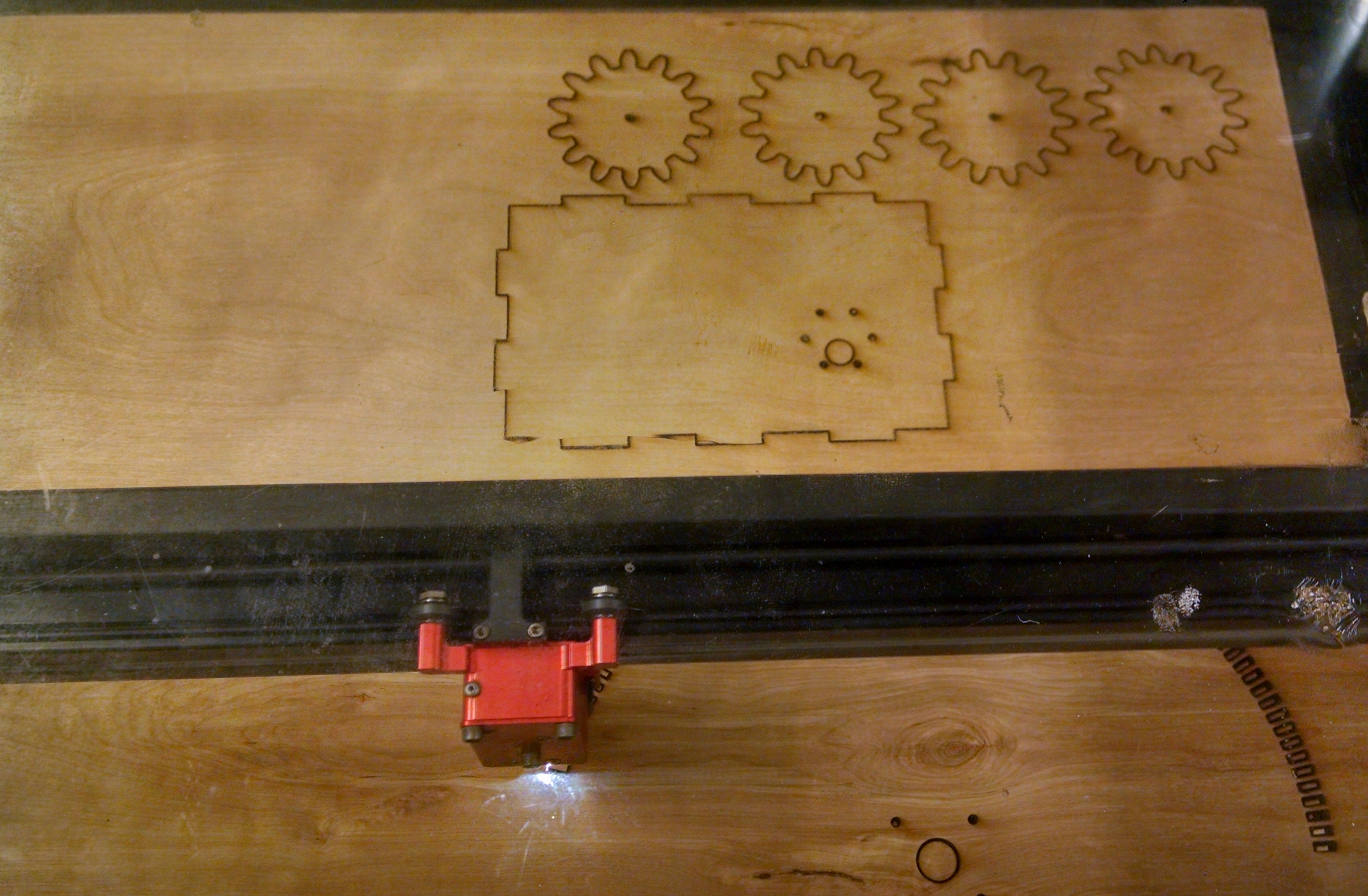
I knew laser cutting was the way to go on this from the start since it’s fast and makes big, sturdy parts. I designed the whole structure to be laser cut in Solidworks, and then blasted the whole thing out on the Cal Poly laser cutter in about 20 minutes (My laser still isn’t running yet, I know, tsk tsk). I was even able to laser cut gears and optical encoder grating right into the structure. This is nice since I’m a cheap college student, and it’s cool.
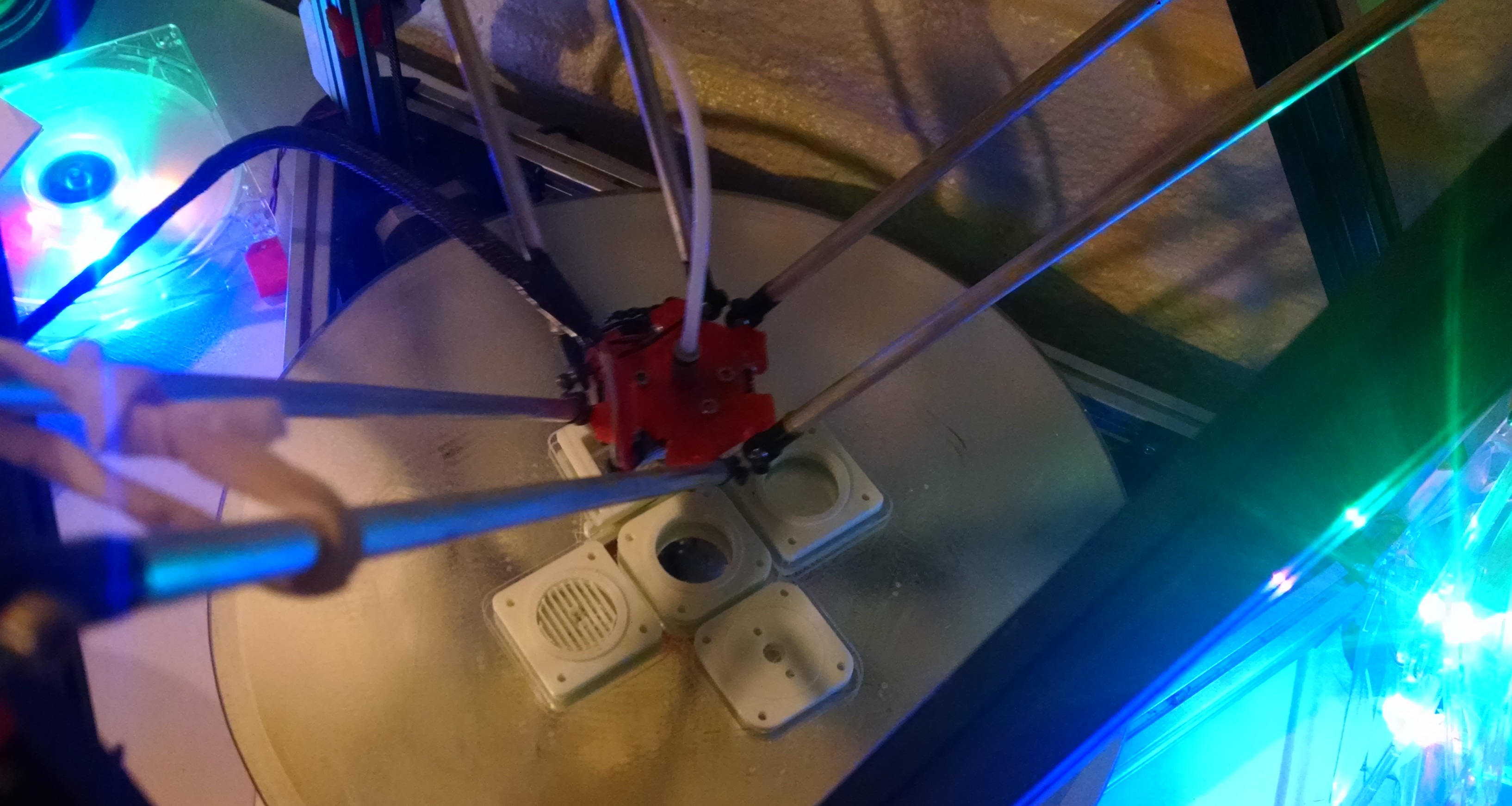
3d printing is a perfect companion to laser cutting in this project. The laser can put up the structure in broad strokes, giving you a big, cheap, and solid framework to build upon. I then printed a handful of doodads that required more complex geometries. Honestly I think every one of these printed parts could be redesigned to be laser cut, most likely as stacks of discs that are then glued together, but I didn’t have the time to do that. We were on a tight 2 week development schedule, and I wasn’t able to reserve the laser till a few days in, which meant speed was number one.
Here’s some of said doodads. The motor mounts were the biggest 3d printed piece. The altitude tower, as I call it, was given an access door under the plan that all the electronics would be hidden inside it. The original design intent was for the motor to be inside the box too so it was all hidden, but this didn’t happen due to some weirdness with the gear ratios, which we’ll talk about next.
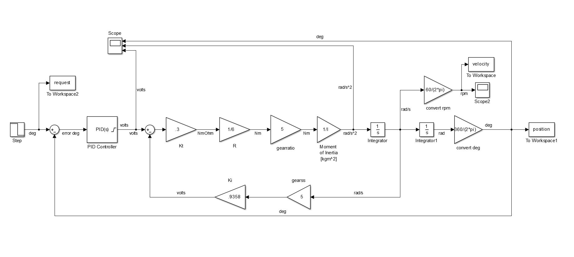
I whipped up a Simulink model to select the best gear ratio for each axis. The model simulates the electric motor and the inertia of a rotary axis. The CG of each axis was aligned with the center of rotation so there was only inertia to deal with. This guarantees the most angular acceleration for your torque-money. The goal here was for the axis to just get up to speed over a 180 degree turn before it had to slow down to the set point. I tested a variety of ratios, and then someone threw a wrench in my fan blades.
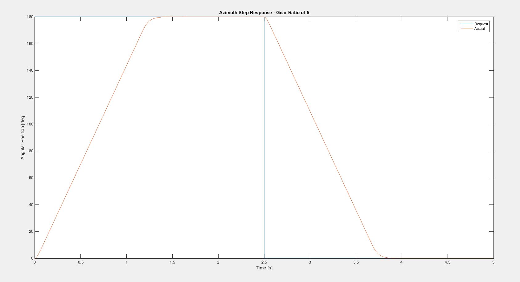
We got these meaty geared DC motors from Amazon. They were cheap, and already geared which was nice. Unfortunately, they were too torquey. We didn’t really need another set of gears, or if we did, they maybe should have even been gearing down. At this point in the design though, such a drastic change in the gearing setup would require a major redesign. If you recall, we were on a two week schedule, and I really couldn’t do that. 1:5 was the smallest ratio I could fit in with the rest of the design. This produced a solid turn, taking just over a second to make a 180 turn, but we could have gotten a little more out of these motors with better gearing.
One of our more unique features was our decision to make our own encoders. We put a pair of IR LEDs and an IR phototransistors in quadrature across our laser cut encoder grating. This was a bit of a cost saving measure, and it eliminates the possibility of slippage or slop on whatever shaft mounted encoder we might have cooked up. turns out encoders are fancier than we realized and this was our Achilles heel. 90% of our time was spent resolving the issues with the encoders.
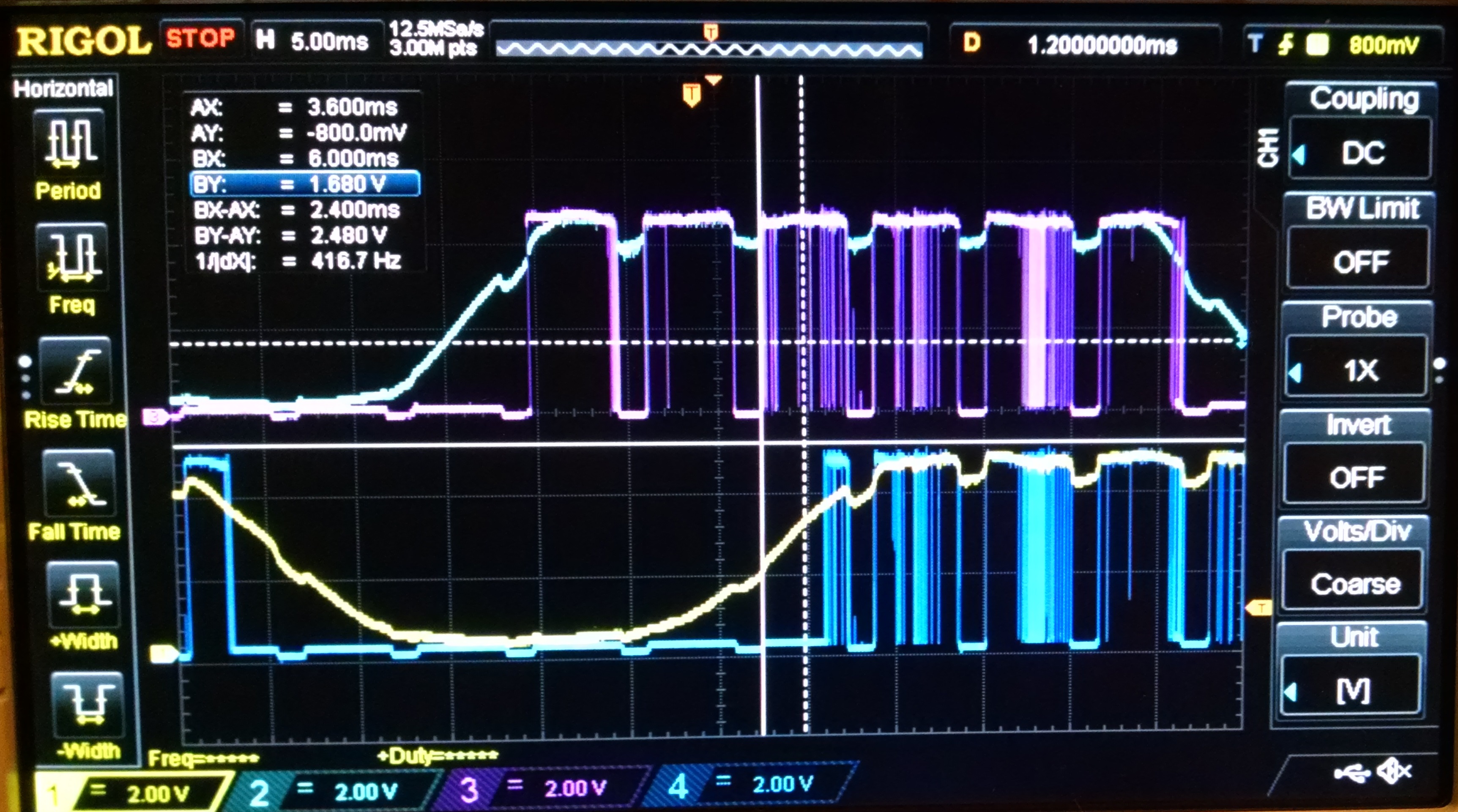
Our encoders signals were fed right into the microcontroller to trigger interrupts. This was the first problem. Our coarse, amateurish encoders produced a very rounded analog type square wave, which does not play nice with interrupts. The solution to this was to add a comparator. That’s where noise reared it’s ugly head. The slow transition through the digital grey area still wrecked havoc with the comparator, and noise caused random transitions all over the place, which is what you see above.
The noise issue seemed to come from a variety of places. The motors, PWM, and finally, the power supply we were using. The motors were the instant first suspect, so we murdered them with bypass caps and a variety of solutions, until it got to the point where they were on an isolated power supply, and PWMed through an optoisolator. With no real connection with the motors, the blame obviously couldn’t be placed on them solely. Eventually the issue was tracked down to the power supply we were using. It was an old linear model, which seemed to start rippling under heavy load. This was hard to see since it never appeared until everything was running, and then you tended to blame some part of the circuit.
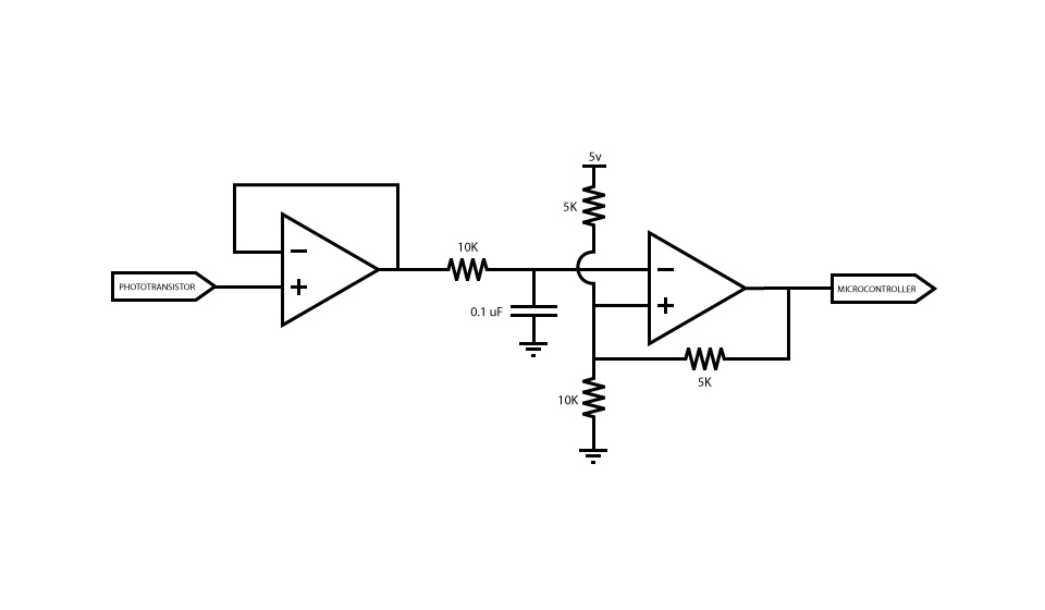
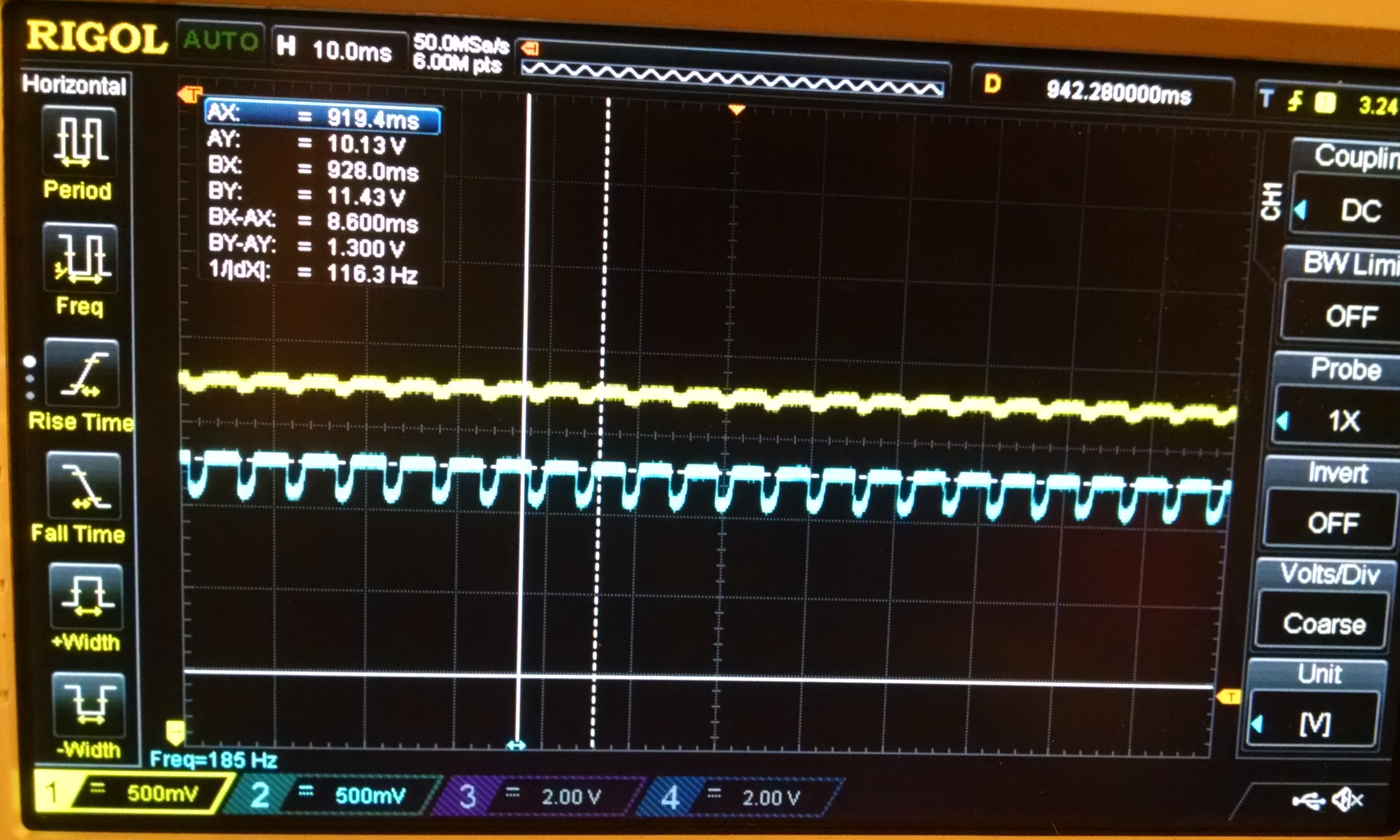
This was the final fix for the encoders. A buffer amp, low pass filter, and Schmitt trigger produced a nice square wave after we eliminated the faulty power supply. I voted that we burn that power supply, given it had cost us several sleepless nights working on the circuit, but it seems it’s sticking around. Lesson learned, don’t trust your equipment implicitly.
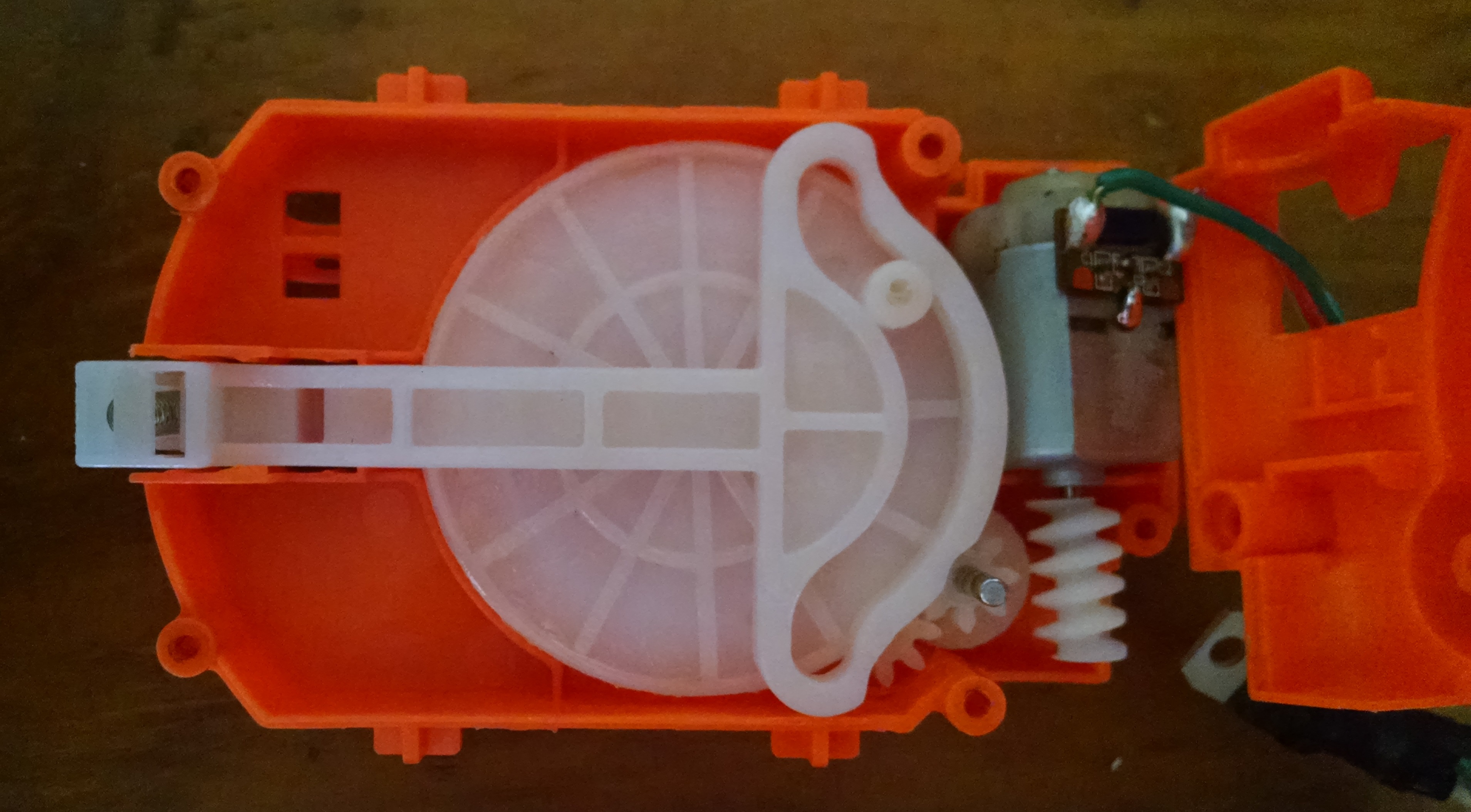
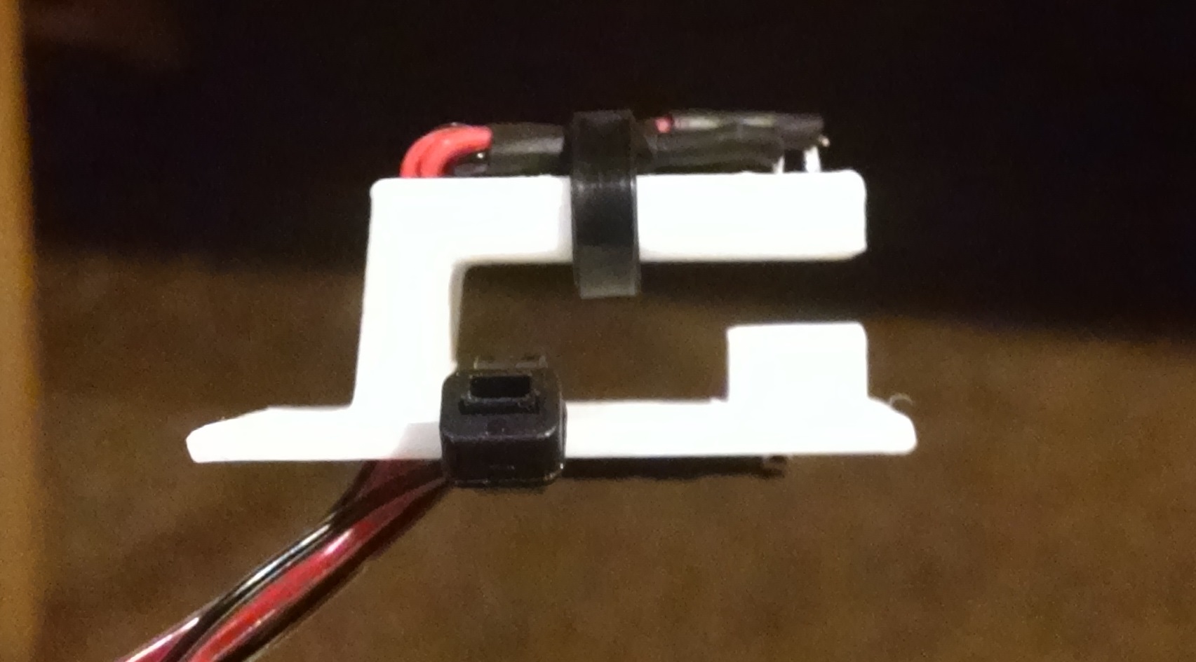
The next goal was to get control of the Nerf gun. We used a CS-18 since it was electric and automatic, under the hope that we could commandeer the circuitry for digital control and avoid pulling the trigger with a solenoid or some contraption. We ripped it apart, and it turned out to be a lot more complicated than you’d expect. We wanted to simply wire a MOSFET across the trigger and digitally yank it, but surprisingly, the trigger was a DPDT. Turned out the Nerf people did this so they could run the flywheels that shoot the darts at a lower voltage at idle, and then a higher when you start shooting to prevent the speed from dropping off under load too much. Clever girl, Nerf. The gun consists of two actuators, a flywheel, and a ram seen above that shoves darts into the flywheels. I was under the impression that the ram was having its voltage switched to push it out and then back in, but it’s actually all mechanical as seen above.
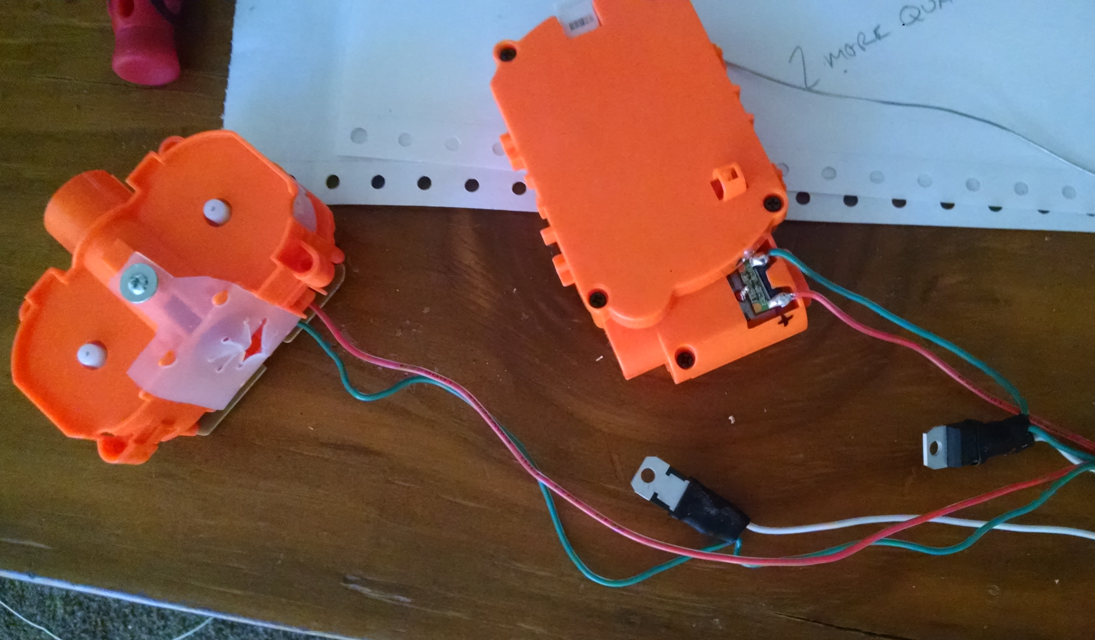
The realization that the pusher was all mechanical meant that we didn’t need to understand the circuit any more and try to use it. Instead, I just butchered it all out and hooked the motors up to voltage through a pair of MOSFETS. This gives us digital control of both rate of fire and how hard you fire.
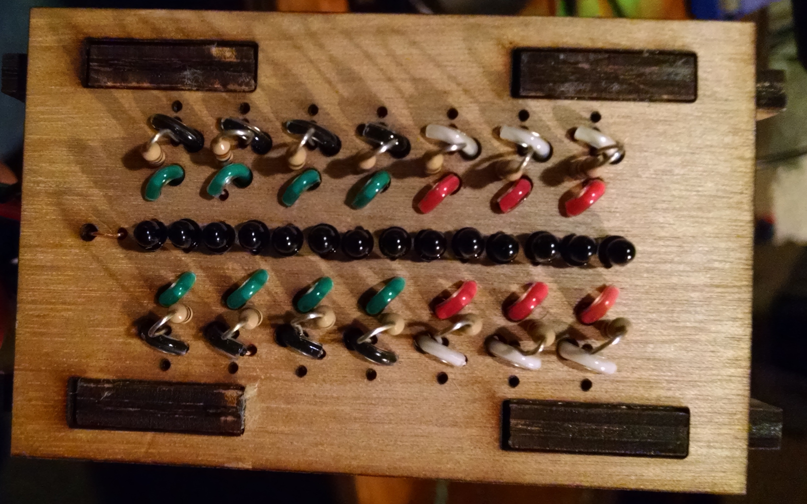
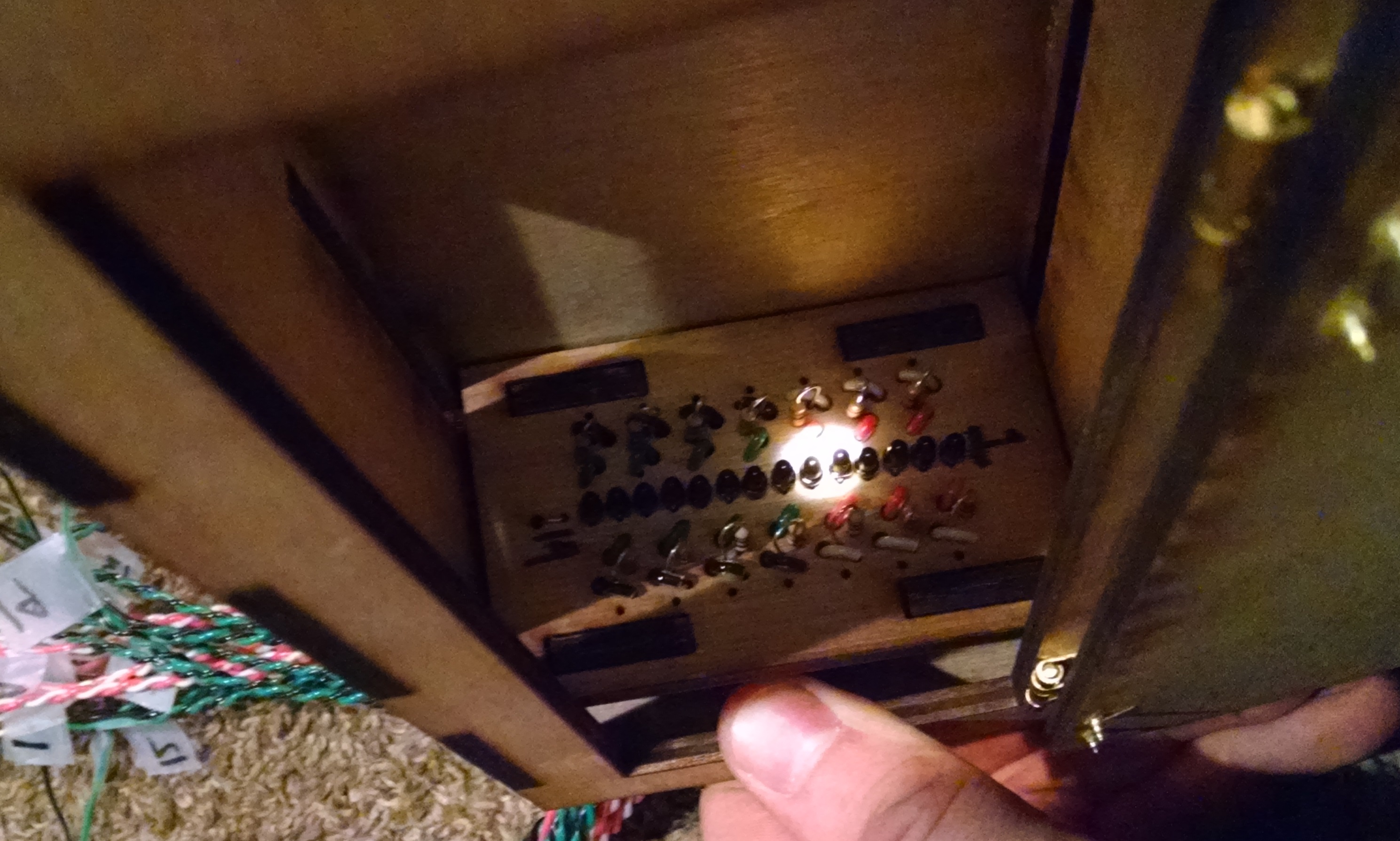
To detect the light we decided to go with a line scanner directly attached on the gun. The gun would simply sweep until it detected a spike in IR light and then it would go back to the spike and then scan vertically in a similar manner. This is a line of 14 phototransistors that make up the scanner. This is a bit of laser cut wood used as a protoboard. Pretty convenient actually. It also had space for a low pass filter on every transistor, but this turned out to not to be necessary, and also impossible without buffering the signals with an op amp since the transistors were super sensitive to loading.
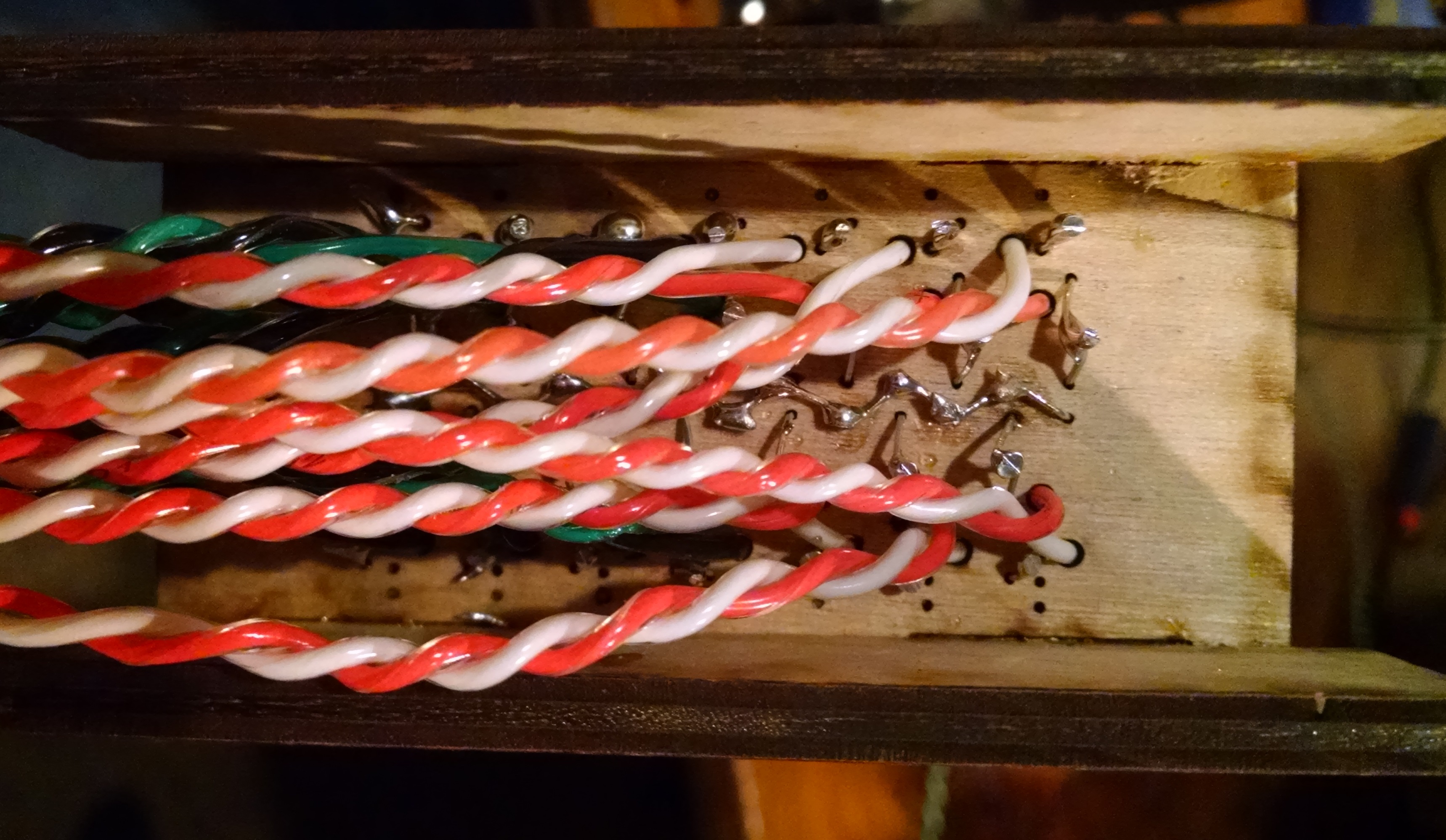
This is my new pastime, twisting wires with my drill. Twirled wires have been clinically shown to satisfy me on some crazy deep subconscious level. Everybody should twist their wires as it makes everything much cleaner and reduces global warming or something.
This is the real meat of the whole sensor assembly. The line of sensors was mounted in slots in a housing with a Fresnel lens on the front of it. The slots allowed me to adjust the sensors to the focal point and then nail them down. This image shows it focusing a light from a can light on the ceiling. With the small automotive bulb we were using for the competition, the focused point was slightly smaller than the head of a phototransistor.
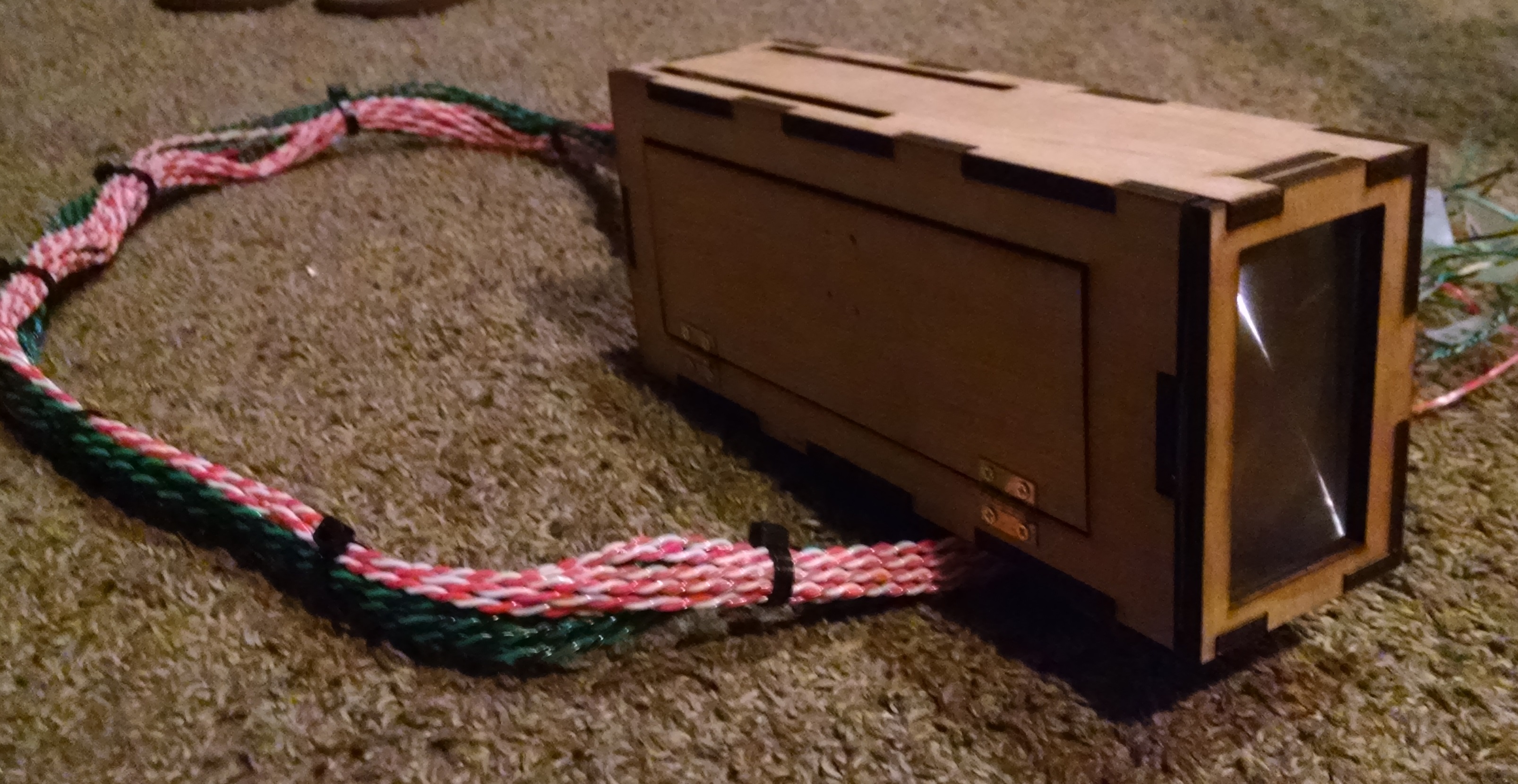
Here is the completed sensor assembly. It’s beautiful. It has a crap load of wires coming out of it. Every transistor shared a common power, but had an independent sense and ground line. This was so that every sense line could be twisted with a ground to lessen interference. Not sure if that actually did anything, but it sure looks cool. You can also see the beautiful Fresnel lens on the front, as well as a pretty little access door to allow you to look at the sensors while adjusting focus.
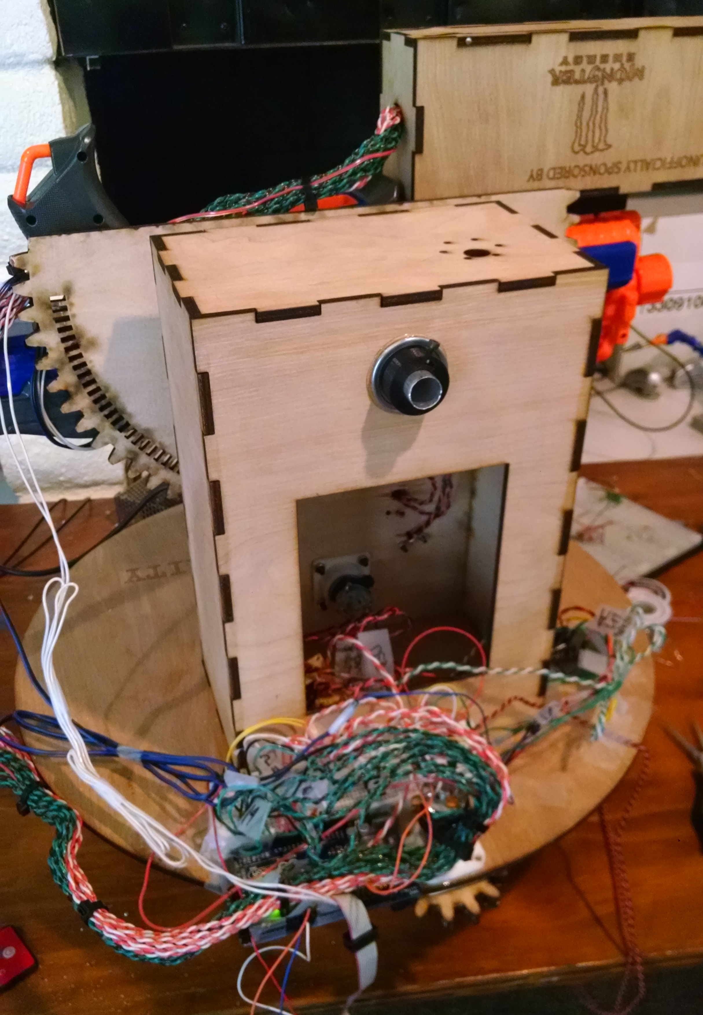
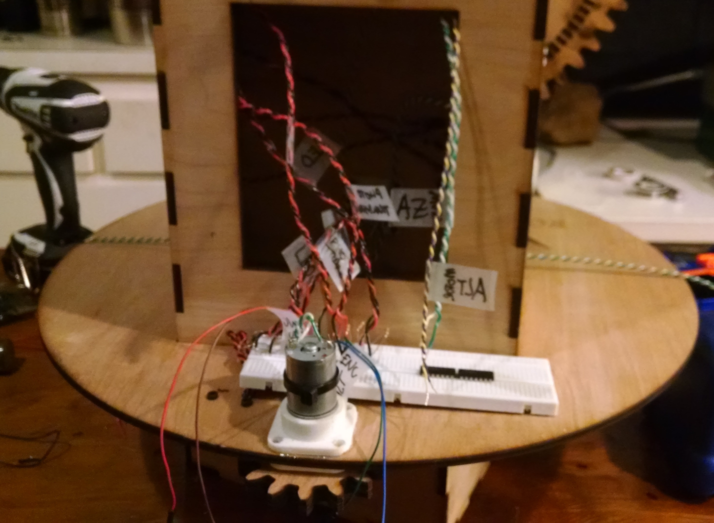
Here it is all put together, the assault of wires from the sensor and h bridge, motors, and encoders. We used a Arduino Mega, hidden under there somewhere. But we didn’t do any of this nonsense in Sketch. We used freeRTOS and C++ to program the gun because we have self respect. The “Unofficially Sponsored by Monster” was a bit of a joke, since we cleaned out Albertsons of Monsters 3 times while working on this project. When we turned it in, we were both running on an hour or two of sleep in over 48 hours.
Desparate for more? Super bored? Read the full report here.
DominicDoty.com and all work shown in it is licensed under a Creative Commons Attribution-NonCommercial-ShareAlike 4.0 International License.