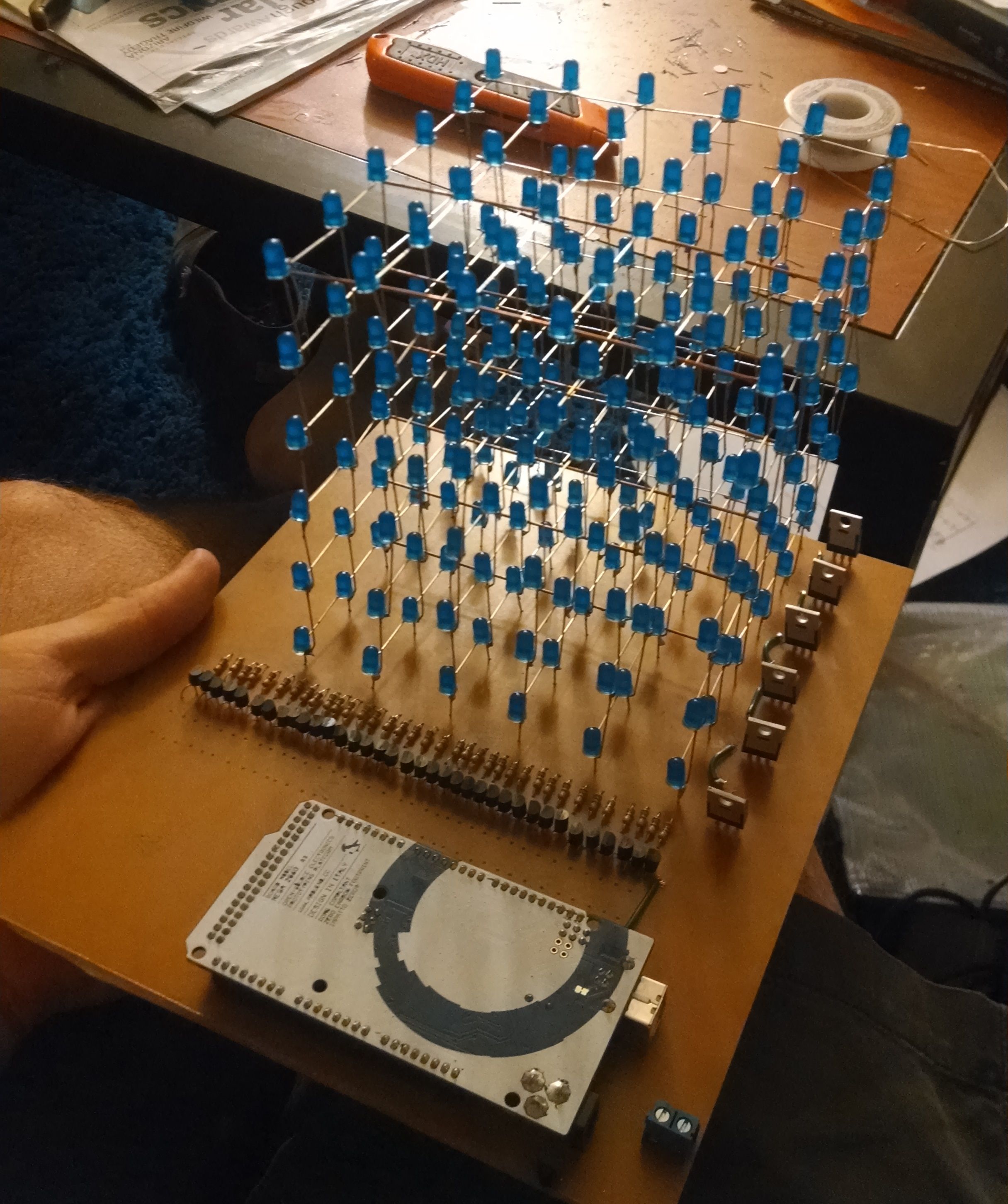
A friend of mine was building a 6x6x6 LED Cube for a class project. He needed some help with a board for the cube, and contacted me because he knew I had made boards.
As I wrote about in an earlier post, I had a modified laminator that I used to make circuit boards in the past. Unfortunately the board decided to burn itself to death. Apparently things are designed to work the way they’re designed to work. This board was also extremely large, using up the entirety of one of my copper blanks, and required many pins. This makes it impossible to use either Diptrace (pin limit) or Eagle (size limit). Short on time, I decided to use Sharpie as an etch resist.
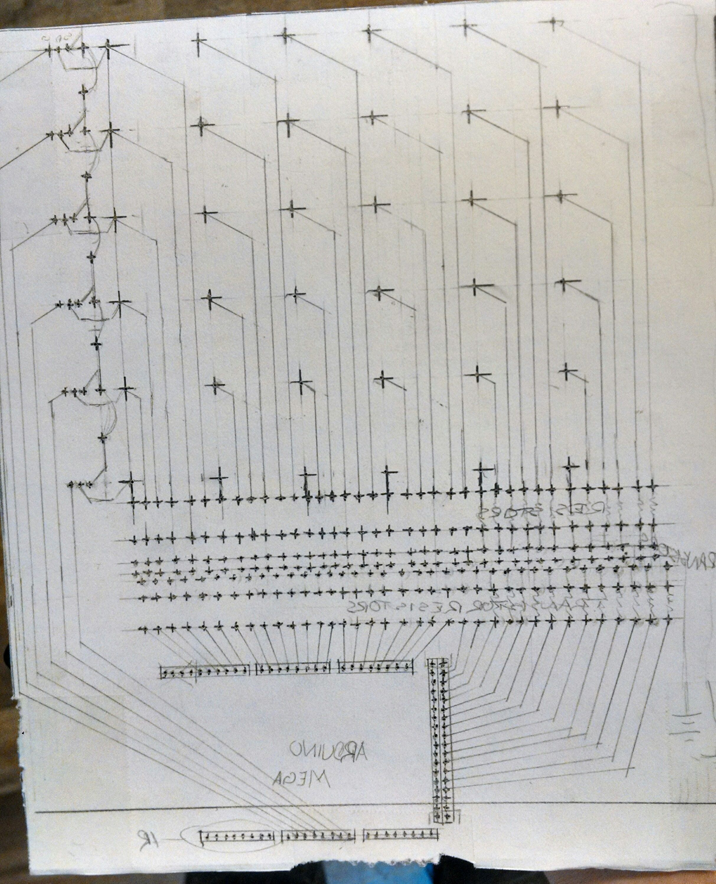
Drawing a board isn’t actually all that crazy for me. I’ve had a few courses on drafting by hand, so plotting out the lines wasn’t very intimidating. I got out my T square and other drafting accoutrement and plotted out the board. At first it was a great experience. I think drawing out a board layout by hand is a great way to force yourself to really think about layout and routing, no auto-route here! That being said, it sucks. It takes a really long time for a board like this. But that was nothing compared to what comes next.
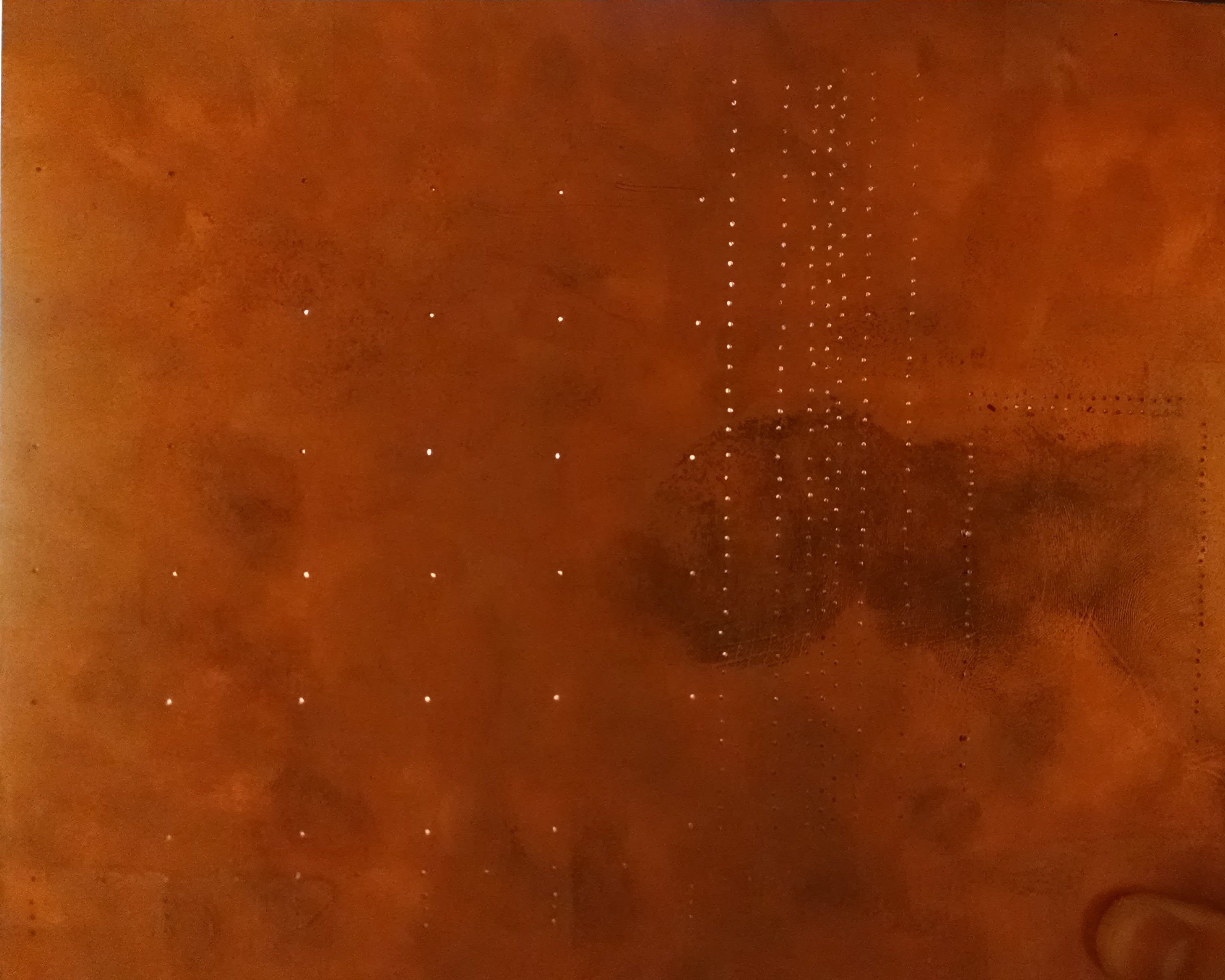
The next step is drilling all the holes for the components. I taped my drafted pattern onto the PCB and drilled away with my fractional millimeter drill bits in my Dremel. This board uses an Arduino Mega, one transistor per column, and one mosfet per layer. That means 36 transistors, 6 mosfets, 72 resistors, and an Arduino Mega. All in all I drilled around 310 holes. God I want a mini mill.
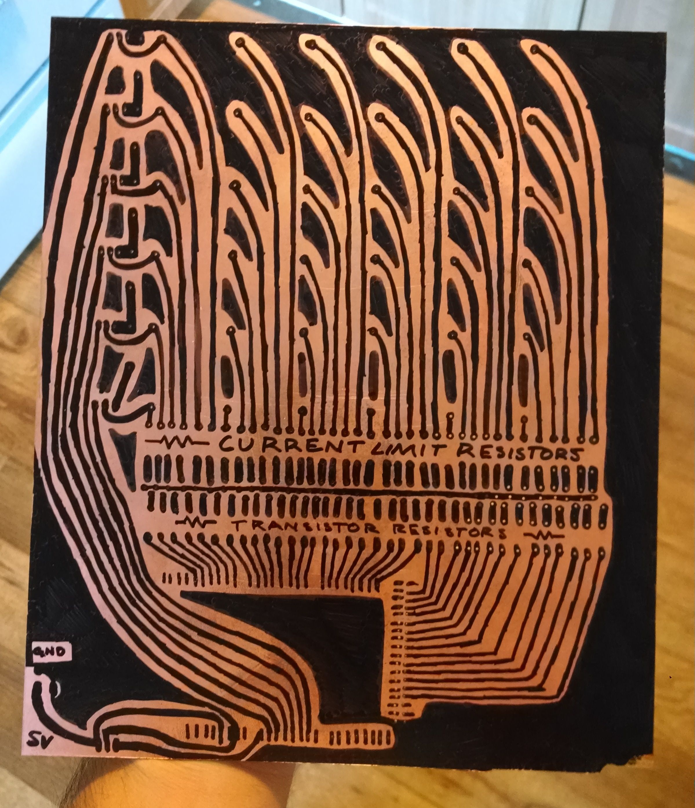
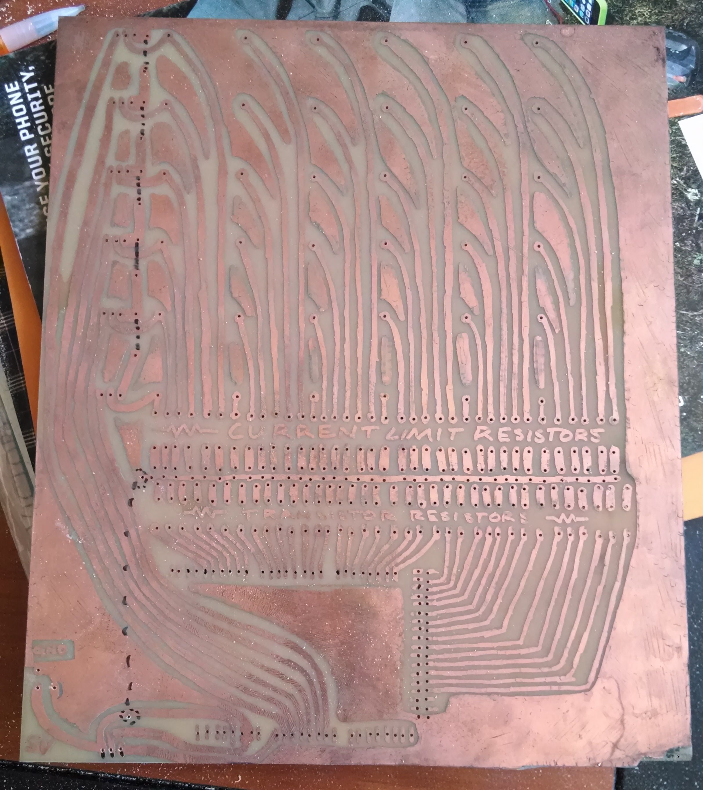
Now I realize, I need to remove the template paper to draw the Sharpie on the board. All that work for the template was just to drill and now needs to be replotted with the Sharpie directly on the copper. I thoroughly cleaned the board to remove oils and dust from drilling, and started drawing with gloves on. At this point, I decided that electrons are dumb. I don’t need a nice straight plotted path all over this board, just A to B. So I started free-handing the lines. I kinda like it, looks sort of art nouveau or something. I also like being able to write random words with the Sharpie and etch them.
The board works! Aesthetically however, it isn’t what I would have liked. I wanted to make the system on two boards, one only with the LED Cube on it as it sits now, and one with all the transistors and the Arduino. They would be connected by a ribbon cable with the copper sides of the boards facing each other. I’d then build a wood edge around it to enclose it all. The frame would have slots routed in it to hold both boards and an external power switch. Maybe paint the non copper sides of the board to make it look a little nicer. But alas, time constraints rule all.