Rear Projection TV Teardown
More Random 18 Mar 2015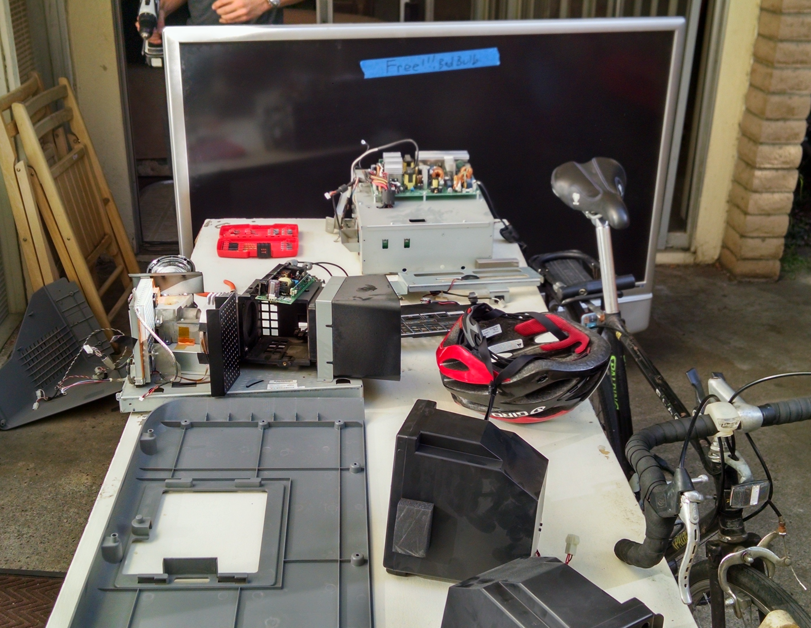
Someone across the street from my apartment left out this perfectly awesome rear projection TV with a “bad bulb”. After it sat there for about a week, I decided to haul it over to my place and take it apart. Old products are a goldmine of random interesting parts, and a great opportunity to take a look at design and manufacturing.
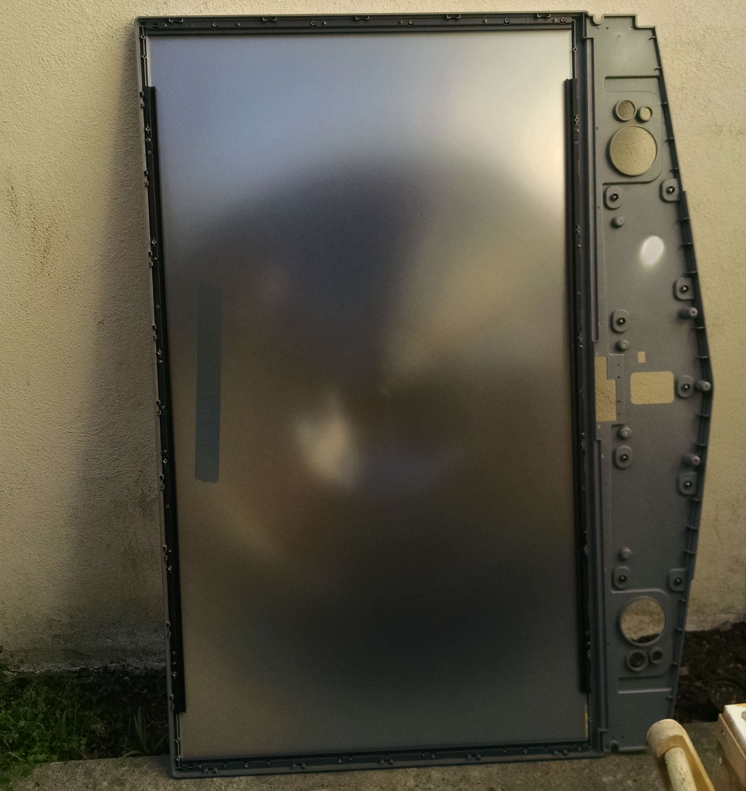
The original prize when grabbing this TV was the screen. Rear projection TV screens are actually a massive Fresnel lens. I had a few small Fresnels from my automated Nerf turret project and quickly discovered that the 3”x2” lenses were capable of burning leaves and marking wood. One of my friends informed me of the massive Fresnel lenses inside projection TVs just as this one appeared across from the apartment. If a tiny one can burn leaves, this one will probably let you start a forest fire with a flash light.
The TV was DLP which stands for Digital Light Processing from Texas Instruments. DLP is one of the two ways to project an image. One method is to selectively block light, like an overhead, while the other is DLP in which light is selectively reflected by an array of tiny micro mirrors and magic.
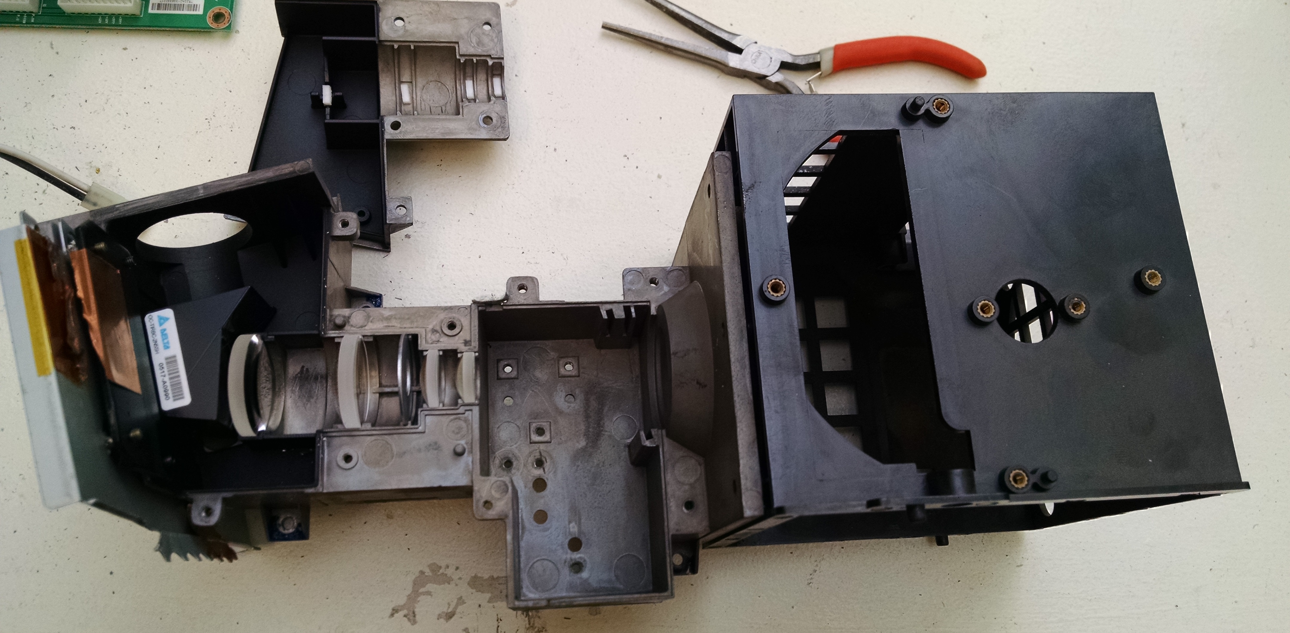
This is the box that holds the meat of the DLP setup and optics. The far right is the box that the light source goes in. The light is directed though a little tube of mirrors, which aren’t shown, probably to roughly collimate it. The empty space at center is where the color wheel goes, which we’ll talk about next. At left there are 4 lenses to prepare the light for the DLP chip, expanding the beam so it is roughly the size of the DLP chip. The black housing on the far left is where the DLP chip lives, sitting at a 45 degree angle to the optical path, selectively reflecting light up in the photo to the next optical elements.
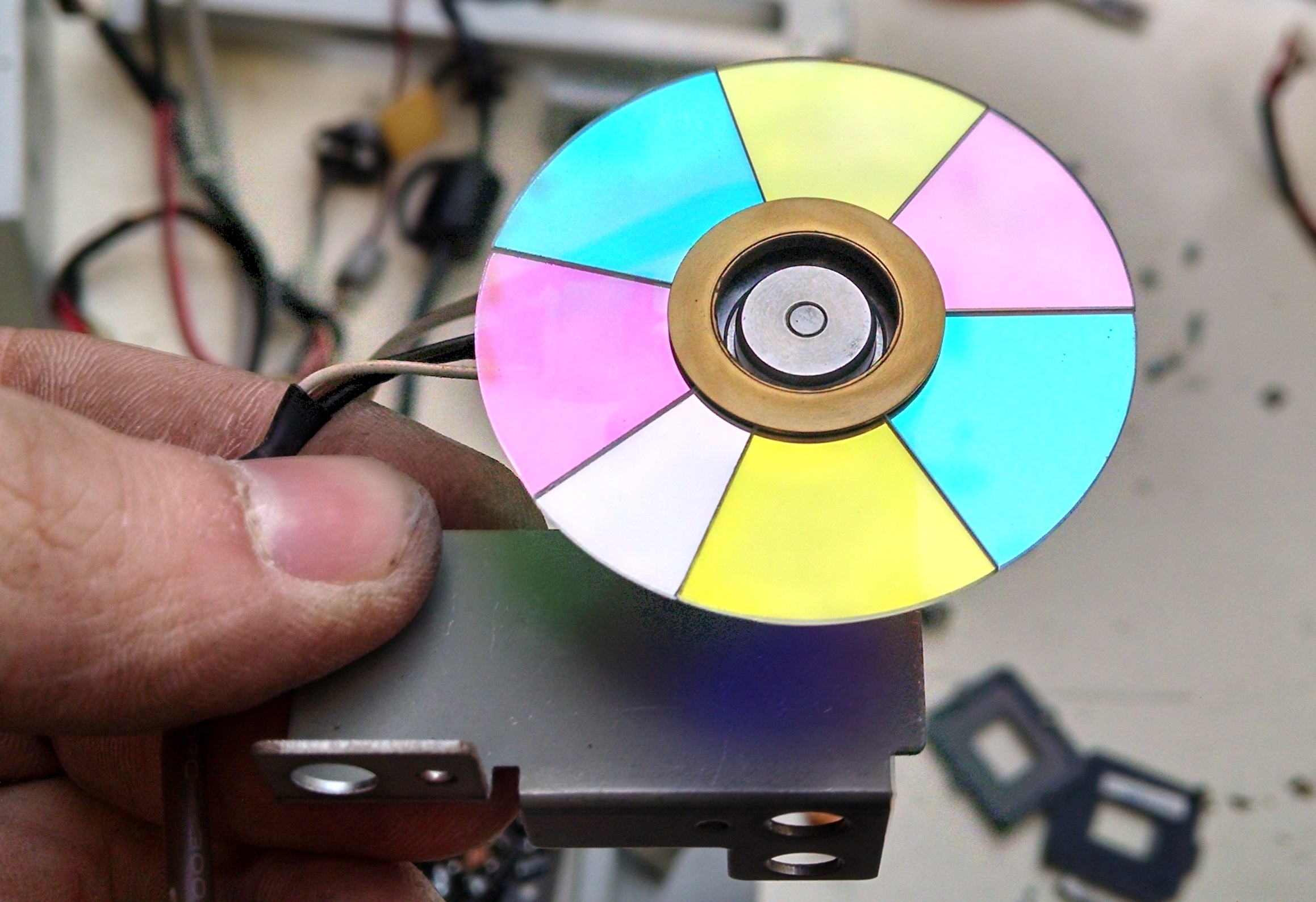
This is the color wheel. Remember how we said that the DLP chip selectively reflects light? Well the light source is white light, and the DLP mirrors can’t change the color, so you need some way to make the colors we see. This wheel is sort of CMYK or cyan, magenta, yellow, and key (black), except the key is different. In projection as opposed to printing black is actually just the absence of light, and is instead substituted by a white or clear band. I’m guessing that this allows the projector to put out a nice bright white color if it ever needs it. The clear band is smaller than the others and only occurs once. Again just my thoughts here, but that is likely because the other colors combined will make white light, so the additional ultra white is only a supplement.
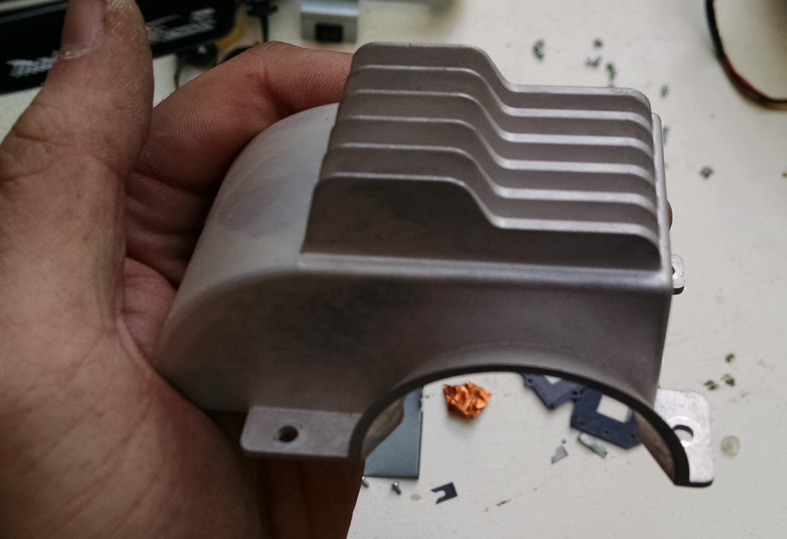
I liked this part because it’s a nice example of a die-cast part. The surface finish and coloring of this part is pretty typical of a die-cast part with its sort of mottled exterior. You can also sort of see the draft on all the fins on the top. This is a good indication of where the halves of the mold were. This one is pretty obvious, the parting line runs around the bottom edge of the part and up along the semicircle in the center.
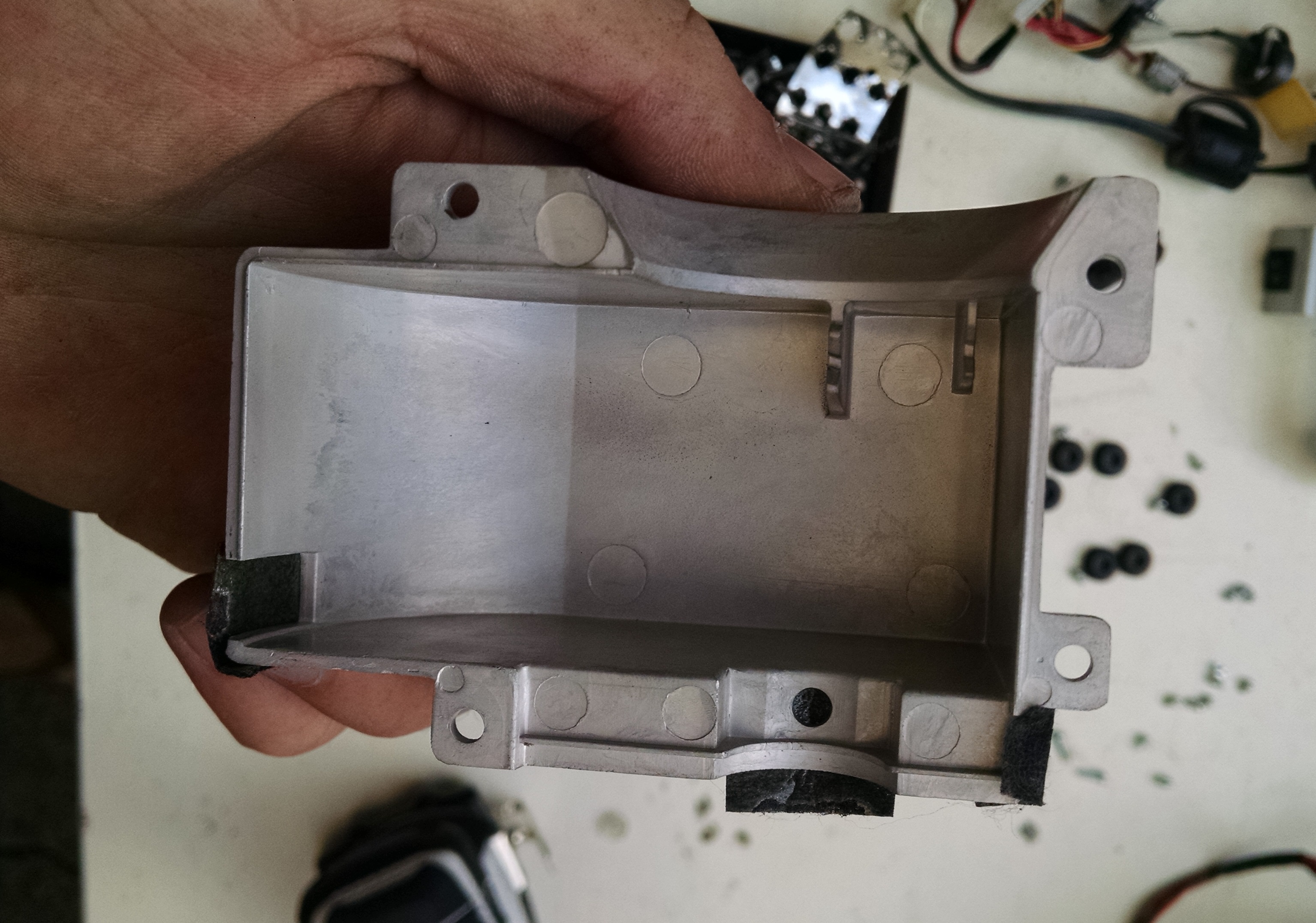
Here is the real dead give-away on die casting though, the witness marks. These marks come from the pins used to shove the hot metal part out of the mold. You can also see the draft on this area of the part, further reinforcing the part line location. You can’t see it in the photo, but there is also a little flash, or extra material, from where the two halves of the mold join imperfectly. Injection molding plastic is actually an extremely similar process but with plastic instead of metal. The plastic molds however, are typically crazy complicated. Injection molds typically have a number of lifters which are moving subsections of the mold that allow you to mold undercuts, or places where the part would typically end up stuck on the mold. Lifters are easily seen as small square indentations under an overhang such as a clip protruding from a wall.
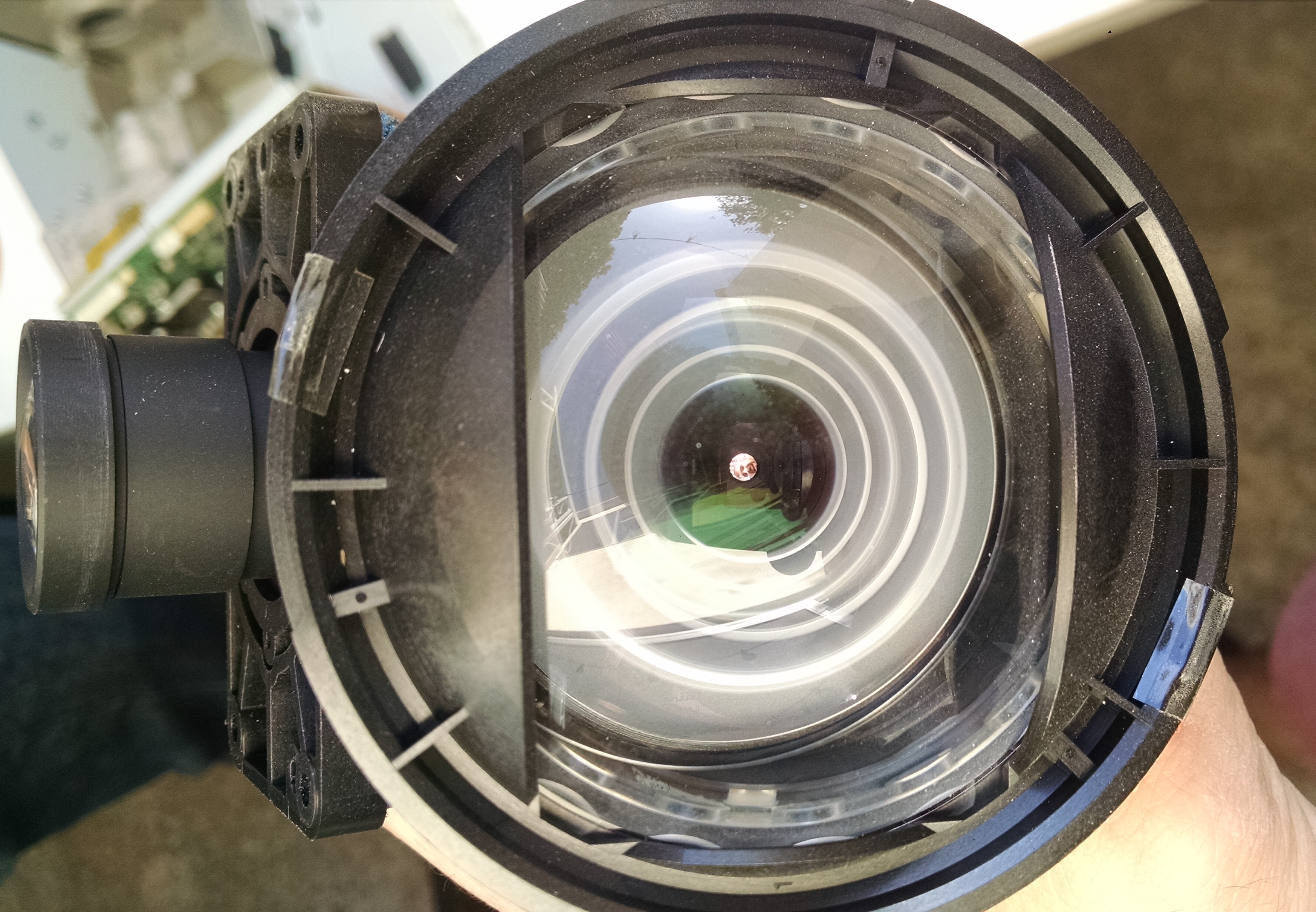
This was a bit of a pretty surprise. This is one of the final lenses of the DLP train. This lens throws the image out towards the back of the tv. That huge slanting back of rear projection TVs is actually a big shiny mirror that reflects the image towards the front screen and its Fresnel lens. The Fresnel straightens out the expanding light rays from this lens into a collimated beam straight to your brain. If you look carefully at this picture, you can see Michael, who took the TV apart with me.
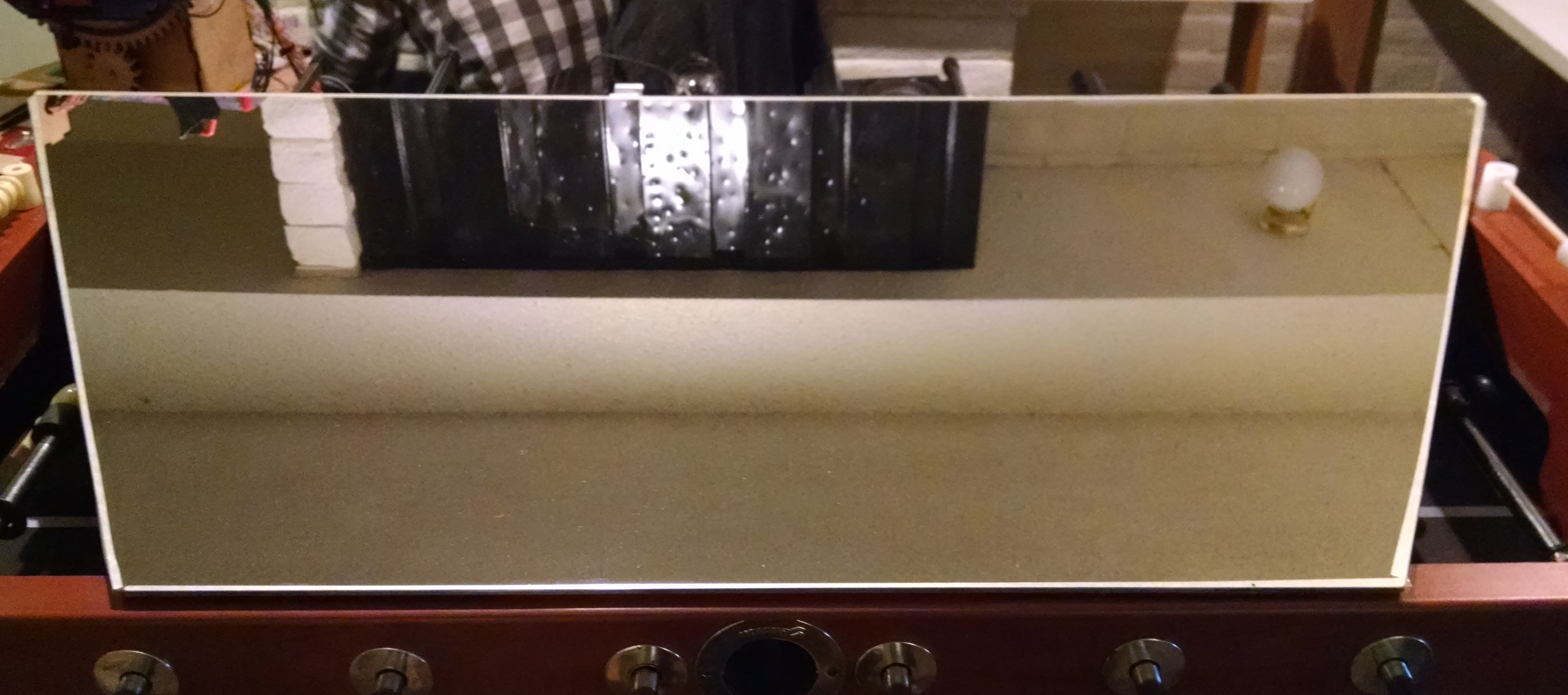
This is said giant shiny mirror from above. This sits right up against the angled back of the TV. It was exceptionally clean and pretty, since it is a first surface mirror. First surface mirrors are nice since the glass doesn’t interfere with the light like a normal mirror, where the reflective surface is on the back of the glass. I can’t quite put a finger on it, but the image quality definitely feels nicer than a normal mirror.
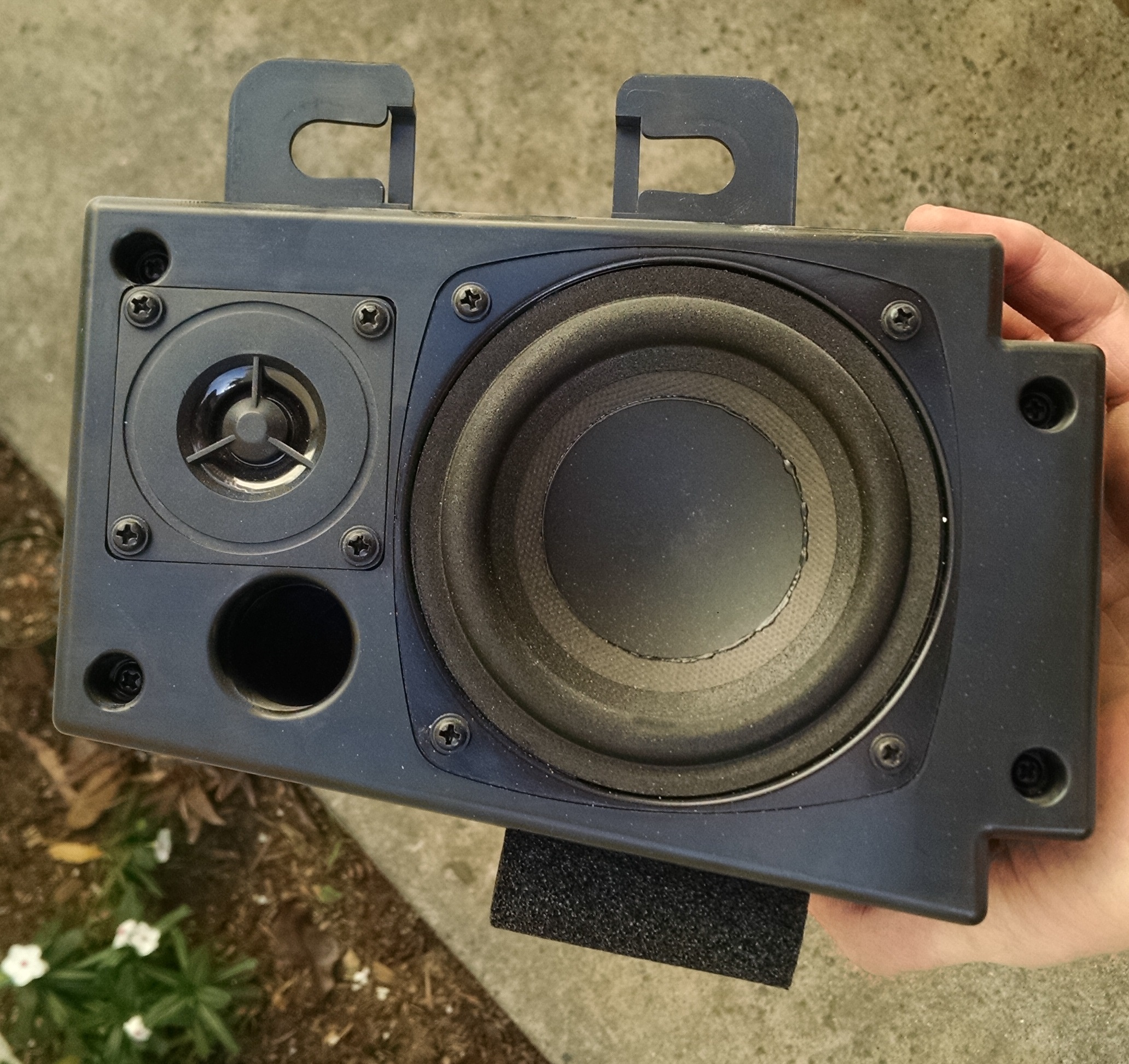
The TV also had two of these ported speaker boxes. Perfect size and shape to make some little bookcase speakers maybe. But probably not worth the effort, since the speakers are probably pretty low quality.
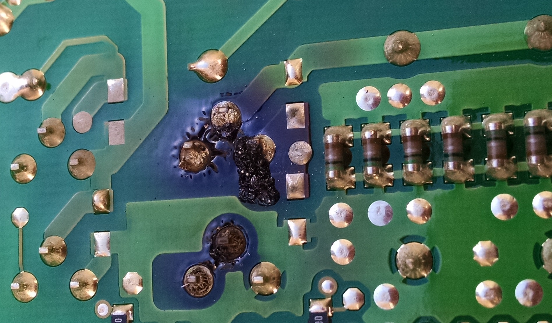
The TV had a note on it that said “bad bulb”. While we were tearing it apart however, we spotted this on the light driver board. Looks like the bulb wasn’t the only problem, or might have been fully functioning. This pair of FETs looked like they gave up the ghost for whatever reason. At this point we had destroyed too much of the TV to fix it and put it back together. In addition, lamps for this TV cost about $80 and I had no use for the TV and didn’t think it would sell for that much to make fixing it worth the time. Plus there is always the chance that those FETs took something else with them when they blew, which would really kill the whole idea.
DominicDoty.com and all work shown in it is licensed under a Creative Commons Attribution-NonCommercial-ShareAlike 4.0 International License.